- 您现在的位置:买卖IC网 > Sheet目录1229 > MCP215X/40EV-DB (Microchip Technology)BOARD DEMO FOR MCP215X/40
�� �
�
�MCP215X/40 Developer’s Daughter Board User’s Guide�
�2.5.2.1�
�MCP215X� IrDA� ?� PROTOCOL� STACK� CONTROLLER� DEVICE�
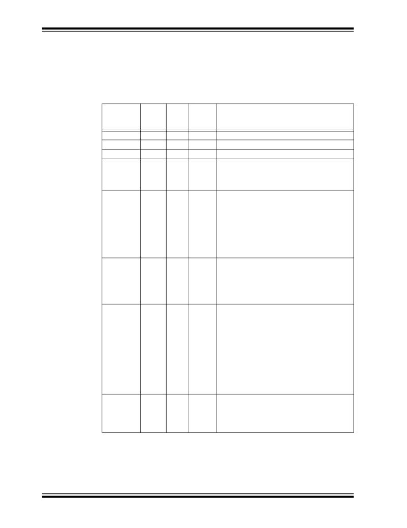
�The� key� signals� for� the� MCP2150-to-microcontroller� (Host� UART)� interface� are� shown�
�in� Table� 2-6,� while� Table� 2-7� shows� the� same� signals� for� the� MCP2155.� The� operation�
�of� the� Host� UART� interface� is� slightly� different� for� the� MCP2150� and� the� MCP2155.�
��TABLE� 2-6:�
�MCP2150� HOST� UART� INTERFACE� PINS�
�Pin�
�Name�
�TX�
�RX�
�RI�
�DSR�
�Pin�
�Number�
�(PDIP)�
�8�
�9�
�10�
�11�
�Pin�
�Type�
�I�
�O�
�I�
�O�
�Buffer�
�Type�
�TTL�
�—�
�TTL�
�—�
�Description�
�Asynchronous� receive;� from� Host� Controller� UART.�
�Asynchronous� transmit;� to� Host� Controller� UART.�
�Ring� Indicator.� The� value� on� this� pin� is� driven� high.�
�Data� Set� Ready.� Indicates� that� the� MCP2150� has�
�completed� reset:�
�1� =� MCP2150� is� initialized.�
�0� =� MCP2150� is� not� initialized.�
�DTR�
�12�
�I�
�TTL�
�Data� Terminal� Ready.� The� value� of� this� pin� is�
�ignored� once� the� MCP2150� is� initialized.� It� is�
�recommended� that� this� pin� be� connected� so� that�
�the� voltage� level� is� either� V� SS� or� V� CC� .�
�At� device� power-up,� this� signal� is� used� with� the�
�RTS� signal� to� enter� device� ID� programming.�
�1� =� Enter� device� ID� programming� mode�
�(if� RTS� is� cleared).�
�0� =� Do� not� enter� device� ID� programming� mode.�
�CTS�
�13�
�O�
�—�
�Clear-to-Send.� Indicates� that� the� MCP2150� is�
�ready� to� receive� data� from� the� Host� Controller.� This�
�signal� is� locally� emulated� and� not� related� to� the�
�CTS/RTS� bit� of� the� IrDA� ?� standard� Primary� device.�
�1� =� Host� Controller� should� not� send� data.�
�0� =� Host� Controller� may� send� data.�
�RTS�
�14�
�I�
�TTL�
�Request-to-Send.� Indicates� that� a� Host� Controller�
�is� ready� to� receive� data� from� the� MCP2150.� This�
�signal� is� locally� emulated� and� not� related� to� the�
�CTS/RTS� bit� of� the� IrDA� ?� standard� Primary� device.�
�1� =� Host� Controller� not� ready� to� receive� data.�
�0� =� Host� Controller� ready� to� receive� data.�
�At� device� power-up,� this� signal� is� used� with� the�
�DTR� signal� to� enter� device� ID� programming.�
�1� =� Do� not� enter� device� ID� programming� mode.�
�0� =� Enter� device� ID� programming� mode�
�(if� DTR� is� set).�
�CD�
�19�
�I�
�ST�
�Carrier� Detect.� Indicates� that� the� MCP2150� has�
�established� a� valid� link� with� a� Primary� Device.�
�1� =� An� IR� link� has� not� been� established�
�(No� IR� Link).�
�0� =� An� IR� link� has� been� established� (IR� link).�
�DS51591A-page� 24�
�Legend:� TTL� =� TTL� compatible� input�
�I� =� Input�
�ST� =� Schmitt� Trigger� input� with� CMOS� levels�
�O� =� Output�
�?� 2006� Microchip� Technology� Inc.�
�发布紧急采购,3分钟左右您将得到回复。
相关PDF资料
MCP215XDM
BOARD DEMO FOR MCP215X
MCP23X08EV
BOARD EVALUATION FOR MCP23X08
MCP23X17EV
BOARD EVAL FOR MCP23X17
MCP2515DM-PTPLS
BOARD DAUGHTER PICTAIL MCP2515
MCP3905EV
BOARD DEMO FOR MCP3905
MCP402XEV
BOARD EVAL FOR MCP402X
MCP42XXEV
BOARD EVALUATION MCP42XX
MCP43XXEV
BOARD EVALUATION MCP43XX
相关代理商/技术参数
MCP215XDM
功能描述:界面开发工具 MCP215X Data Logger Demo Board RoHS:否 制造商:Bourns 产品:Evaluation Boards 类型:RS-485 工具用于评估:ADM3485E 接口类型:RS-485 工作电源电压:3.3 V
MCP2200
制造商:MICROCHIP 制造商全称:Microchip Technology 功能描述:USB 2.0 to UART Protocol Converter with GPIO
MCP2200_11
制造商:MICROCHIP 制造商全称:Microchip Technology 功能描述:USB 2.0 to UART Protocol Converter with GPIO
MCP2200_13
制造商:MICROCHIP 制造商全称:Microchip Technology 功能描述:USB 2.0 to UART Protocol Converter with GPIO
MCP-220-00001-01
制造商:Supermicro Computer Inc 功能描述:HOT-SWAPPABLE HARD DRIVE TRAY BLACK - Bulk
MCP-220-00001-03
制造商:SUPER MICRO COMPUTER, INC. 功能描述:HOT-SWAP 3.5" DRIVE TRAY, SILVER - Bulk
MCP-220-00001-03(01)
制造商:SUPER MICRO COMPUTER, INC. 功能描述:SUPERMICRO SCA TRAY, BLACK - Bulk
MCP-220-00003-01
制造商:SUPER MICRO COMPUTER, INC. 功能描述:1U SPARE HOT SWAP DRIVE- BLACK (2ND GENERATION) - Bulk